
Бесплатный фрагмент - Thermoelectric Microgenerators
Optimization for energy harvesting
Preface
The idea for this book came from the experience. Our team is in thermoelectric business for over 20 years. Firstly, for many years it was thermoelectric cooling solutions for miniature applications. In recent years, thermoelectrics moves in microgenerators trend. Green energy, energy harvesting…
Promising directions — applications of thermoelectric microgenerators for tasks of low energy — recycling waste heat surrounding thermal sources, of human body energy harvesting and so on.
This direction only began its development. Of course, there are many ideas for development come from inventors and scientists. Often an absence of sufficient knowledge and understanding of the subject of thermoelectricity is compensated by enthusiasm, the broadest fields of promising applications, interesting tasks.
Numerous appeals of such potential consumers to assist them in thermoelectric solutions usually are accompanied by neediness of detailed technical consulting from fundamental physical base of the thermoelectricity phenomenon till fine nuances in their applications.
It has given rise to the idea of writing of the reference book FAQ (Frequently Asking Questions) on the most important questions. Gradually this idea has developed into the separate book on the volume of the reference material.
The structure of this book contains detailed explanations addressed to a wide range of readers, which for the most part are not specialists in the field of thermoelectricity, of the basic ideas, important aspects of the practical application of thermoelectric microgenerators in the tasks in energy harvesting. I will be glad, if this book will serve as a reference tool in developing appropriate solutions.
Every Chapter was considered as a separate small manual, easy for an inexperienced user to find answers to their particular questions without resorting to detailed studying of the all material of the book. Therefore, the repetition takes place in formulas and expressions from Chapter to Chapter, for example.
Professionals may also say about excessively detailed clarification of “simple” basics of thermoelectricity. Please, these moments can be simply ignored.
But exactly simple and detailed explanations of important aspects of the application of thermoelectric microgenerators and was the purpose of this book. Many formulas, but their detailed explanations, I hope, will help users understand the issues of interest to them.
Chapter 1. Introduction
Creation of alternative, first of all renewable, power sources is the perspective direction of development of power engineering in the world now. The whole direction under definition “green power” (green energy) was appead.
It is the power engineering based on renewable natural sources of heat, causing the minimum damage to the environment, safe and eco-friendly. The big section of new power engineering is the direction of utilization of waste heat of the sources surrounding the person. Including, very interestingly, — thermal emission of a human body.
It should be noted that due to the nature of these heat sources, this is small power engineering. It received a general definition- energy harvesting.
To transform the energy of such energy sources it is possible to use devices that are based on different physical principles: electrodynamic, photovoltaic (small solar panels), piezoelectric and thermoelectric (microgenerators).
Every of the above types of energy converters has its advantages and disadvantages at the same time. And mostly they still compete for the tasks of energy harvesting at the level of concepts and laboratory projects.
Thermoelectric (TE) converters, thermoelectric generators (TEG) have several advantages over other mentioned:
— “omnivore” — convert any weak heat flow, all sources, including the heat of the human body.
— all-weather is not dependent on the daylight cycle (as solar panels).
— latent installations, due to the very small size, which is important for masking.
— highest reliability and long service life (over 25 years).
— no moving parts, no noise, do not need periodic maintenance.
In accordance with recent forecasts [1], [2], the direction of thermoelectric converters of thermal energy in the coming years will be developed into a large segment of the world market with a volume of about 1 billion dollars to 2024 (see Chapter 17).
Thermoelectric generators have, as we know, very low conversion efficiency, which is no more than 15–20% of the Carnot cycle efficiency. It is only few percent of conversion of energy from a heat source.
In energy harvesting applications, where natural heat sources have a slight temperature, generator is working at very low temperature differences and therefore, a fortiori, with very low levels of efficiency.
Although it is most commonly “waste” energy and low efficiency seems to be tolerated, but efficiency remains a key challenge of thermoelectric generators
In this regard, optimization of all aspects of device design and materials of thermoelectric generator is a very pressing task of extracting maximum effectiveness in their application.
The primary task is to develop an efficient thermoelectric material. This is a key component of the device as a whole, determining its main parameters. It is important to obtain material with not only high thermoelectric efficiency, but also sufficiently high mechanical properties. It is the task of the semiconductor materials science where there are their approaches, achievements and expectations.
The second task is the optimum design parameters to ensure the effectiveness of the device in general. It includes development of methods of constructing of optimal thermoelectric microgenerators with available thermoelectric materials.
This book discusses a range of aspects of optimization of thermoelectric microgenerators, their applications in directions of energy harvesting. Interrelations of various parameters are demonstrated, various nuances of operation of thermoelectric microgenerators are discussed.
We will discuss thermoelectric generators in whole, but meaning their miniature (micro — is a slang) types suitable for energy harvesting, small-scale power engineering.
Chapter 2. Physical basics
Preface. Key aspects of applications of thermoelectric microgenerators derived from fundamental physical principles underlying their work. These are effects of Seebeck, Peltier, Thompson, and Joule. Accordingly, we start with the physical basics of thermoelectric modules. This Chapter introduces key concepts and parameters of thermoelectric generators.
Heat balance equations
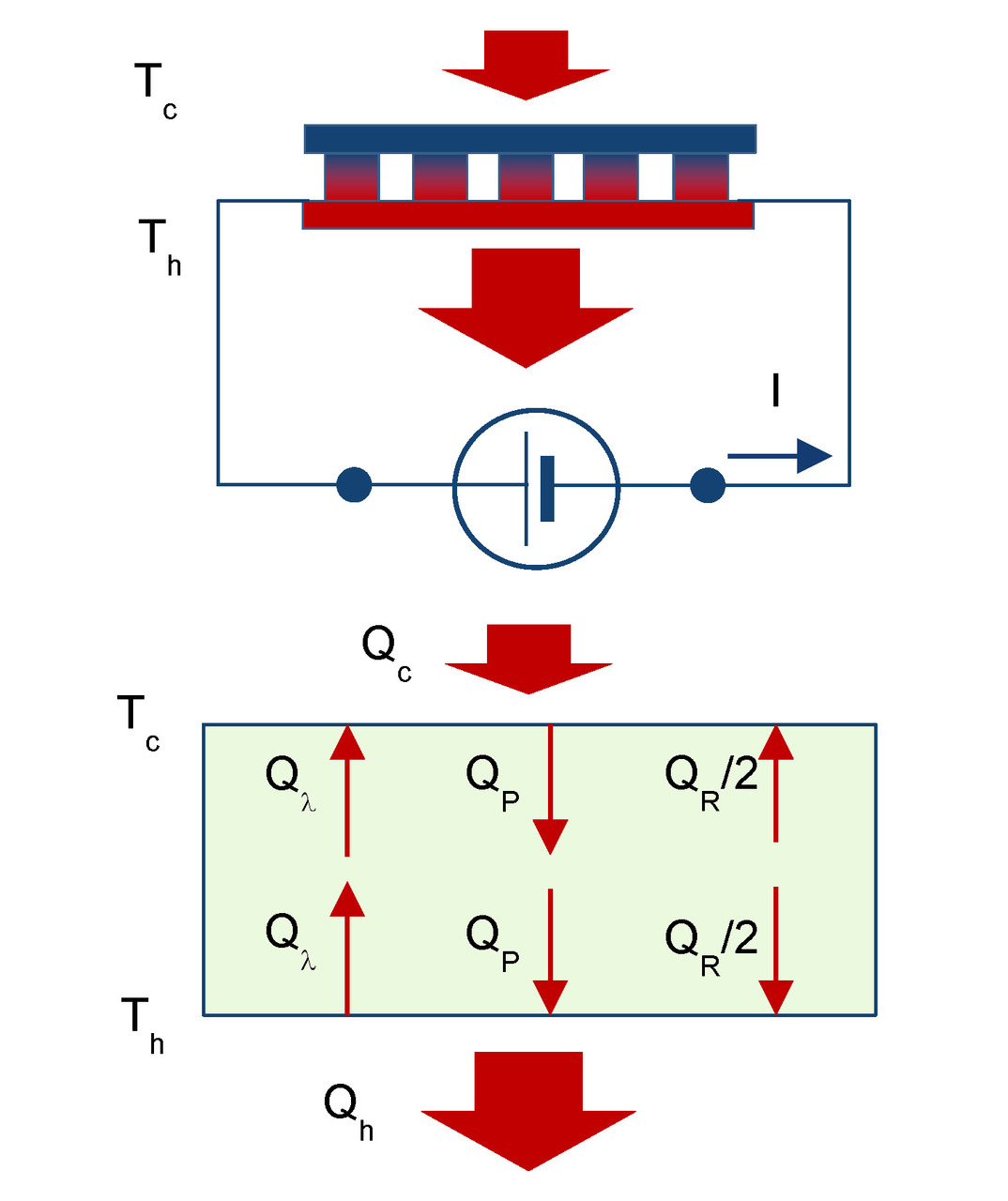
Cooling mode
To date, the widest use of thermoelectric micromodules is connected with cooling of miniature objects — thermoelectric cooling applications.
For comparison, let us give the equations of thermal balance (2.1) — (2.2) of thermoelectric module in cooling mode (Fig. 2.1).

Generating mode
Heat balance equations of thermoelectric module in generating mode (Fig. 2.2) are the following.

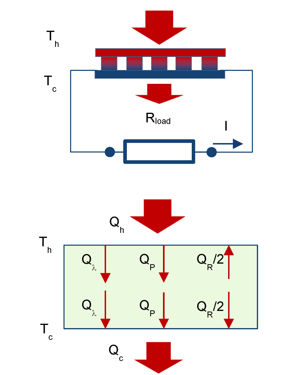
If to neglect temperature dependences of physical parameters, then heat balance equations in the generator mode can be written as the following:

Here and below average values α, k, R are used — average values of paired thermoelements (pellets) of n-and p-type. For example, α= (αn+αp) /2. And these parameters refer to average operating temperature of pellets, in situations where the temperature dependency properties can generally be neglected.
Main parameters
Thermoelectromotive force (ThermoEMF) E of a thermoelectric generator depends on the temperature difference ΔT, number of thermoelements N and Seebeck coefficient α as the following

We introduce the notation for internal resistance of thermoelectric generator ACR=2NR, and for external load resistance — Rload.
Electric current through the generator is determined by thermoEMF E and total resistance of closed circuit (Fig. 2.2):

Here we introduce important parameter m — the ratio of the external load Rload to internal resistance of generator module ACR.

From the balanced equation (2.5) and (2.6) one can find that:

First member EI of the difference (2.10) is the total heat that is converted into electric current by the thermoelectric generator. The second member I2ACR is what part which comes back into heat due to the Joule effect.
— When the difference (2.10) is equally to zero (short circuit mode, external load resistance equal to zero) then all the converted energy comes back into heat.
— When the difference is positive (there is non-zero external load), i.e. the generator converts heat into electricity.
With given ratios (2.7) — (2.9) the balance equations (2.3) and (2.4) can be rewritten as the follows:

Here the heat transferred through the Peltier effect QP

Joule heat Qλ

Voltage U in external circuit, taking into account (2.8), is the following.

Power P in the external circuit (converted power).

Here an important dimensionless factor F is appeared.

Formula (2.16) has a maximum defined by the dimensionless factor F, its dependence on the ratio m (2.9) of load resistance Rloadand internal resistance ACR of generator module (Fig. 2.3).
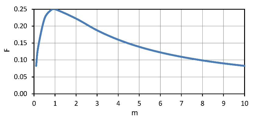
Maximum F and, respectively (2.16), maximum power P are achieved when m=1, i.e.

Important note — maximum power Pmax that can be obtained by a thermoelectric generator module is only one quarter of the power converted by the module in short circuit mode.

Electric current through the module in maximum power mode Imaxat m=1 is the following

The thermoelectric generator efficiency η

Taking into account formulas (2.7), (2.11) and (2.16) one can find that

Investigating the formula for maximum at fixed temperature Thand ΔT (Th, ΔT=const), we obtain formula for maximum efficiency η (optimal mode for efficiency):

Where the optimum ratio of load and internal resistances mopt (mopt=Rload/ACR) can be expressed as the following.

Note, please, the formula (2.24). If maximum power Pmax converted by generator can be achieved when m=1, then maximum efficiency η — at other value of this ratio — mopt (2.24). In the thermoelectric generator, as in any heat engine, maximum power mode operation differs from mode of maximum efficiency.
Effective thermal conductivity and thermal resistance
Heat Q passed through a media, which is the generator, one can write in general using the effective thermal conductivity K” of this media and temperature difference ΔT as the following.

In working generator the heat is Qc (2.12), which differs from the heat transported due to “simple” thermal conductivity Qλ:

Effective thermal conductivity K” differs from conventional thermal conductivity K of agenerator due to the additional Peltier and Joule heat flows, that appear in the working generator, and which are superimposed on the conventional thermal conductivity (Fig. 2.2).
Thermal resistance of the working generator Ȓ’TEG is the following

To a first approximation, at small temperature differences ΔT the 3-rd member (Joule) in the sum in brackets (2.27) can be ignored. Indeed, it can be shown that contribution of this term at small temperature differences is small, no more than 0.5–1%.
Then

Exclusion of a member, depending on ΔT dramatically simplifies analysis of a thermoelectric generator in the tasks of complex ambient. Where the generator is placed between other media and interfaces with different thermal resistance, and it is desirable to optimize the thermal resistance Ȓ’TEG of the working generator (see Chapter 5).
When open electrical circuit takes place in the generator, then there is no Peltier and no Joule heat flows. Only thermal conductivity heat flow takes place. In other words, then Rload=∞ and m=∞ then the formula (2.26) is simplified to:

Temperature difference ΔT at a generator module when an open circuit takes place is associated with heat flow of thermal contuctivity Qλ as the following.

Chapter 3. Optimization of electrical circuit
Preface. Thermoelectric generator transforms thermal energy and gives it to external electric circuit. Here coordination of elements of the electric circuit with parameters of the generator is essential for extraction of maximum power. In this Chapter questions of optimization of the electric circuit are considered.
Basic formulas
Simplified electrical circuit of a generator module is shown in Fig.3.1.
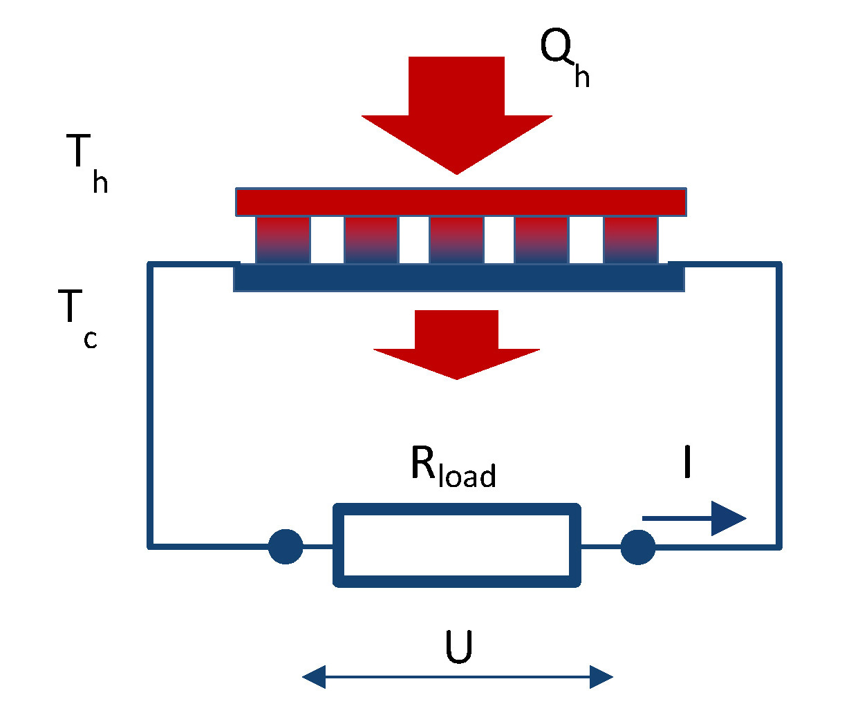
Maximum electric power transformed by a generator from heat source is defined by thermoEMF E and internal resistance ACR of the generator.
The thermoEMF E is found as the following

If to short the electric circuit of the generator (Rload=0), the short-circuit current Isc is

At short-circuit the power Psc allocated in the electric circuit is maximal.

However, all this power will be converted into Joule heat in thermoelements of the generator. In fact, heat converted into electric current returns again into the heat. There is no useful work.
A generator performs useful work when converted power is given out to the external load that has electrical resistance different from zero (Rload> 0).
Then the working current I in the electric circuit (Fig. 3.1) is

Voltage U in the electric circuit, correspondingly

Formula of the net power P has the following form:

Maximum power
From equation (3.6) it follows that the generated power Pnonlinearly dependends on the load resistance Rload.
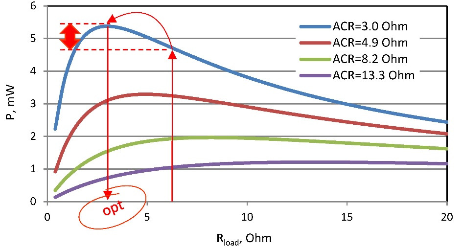
This dependence has maximum power Pmax when external load resistance Rload is equal to internal resistance ACR of the generator (Rload=ACR):
— At given internal resistance ACR of generator, there is an optimal load resistance Rload in terms of maximum power conversion.
— On the other side also follows from the equation (3.6) that at the given loading resistance Rload, the less internal resistance ACRof generator, then more power P (an example, Fig. 3.2 — an arrow up).
— At the same time, for such generator with smaller resistance ACR, there is even more optimal loading (Fig. 3.2 — arrow sideways) with smaller resistance Rload (Fig. 3.2 — red arrow down) which provides even more power.
Maximum power Pmax conversion occurs when:

And corresponding maximum electric current Imax

Comparing (3.2) and (3.3) and (3.7) (3.8) respectively, we get:
— Maximum power Pmax that can be obtained by thermoelectric generator is only one quarter of the maximum available transformed power by the generator (short circuit capacity).

— Electric current Imax through the module in maximum power output is half of short-circuit electric current Isc (3.2).

Chapter 4. Optimization of efficiency
Introduction. In any heat engine the mode of maximum power differs from the mode of maximum efficiency. In this Chapter the operating mode of thermoelectric generator — maximum efficiency is considered in details.
General formula
The value of efficiency η changes with variations of the load resistance Rload similarly to dependence of P vs Rload (e.g., Fig. 3.1). Namely dependence of efficiency η from the ratio m also has a maximum. But this is not the same point as the maximum Pmax. The maximum of η takes place at other value of power Popt somewhat different from the Pmax.
General formula for the efficiency η is the following

Maximum efficiency and maximum power modes
Omitting the detailed math (see Chapter 2), it can be shown that in a simplified form the maximal efficiency ηopt occurs when

In practice, in applications with small temperature differences and typical Figure-of-Merit of generators, the value mopt given by (4.2) is approximately equal to

With regard to the Pmax and Popt — they are pretty close each other.

It should be noted that the efficiency η at maximum power mode and at maximum efficiency mode are also close to each other. It can be shown if the corresponding values mmax and mopt to apply in formula (4.1), respectively, then

Choosing of practically optimal load resistance between maximum power and maximum efficiency modes can be in the range (Fig. 4.1).

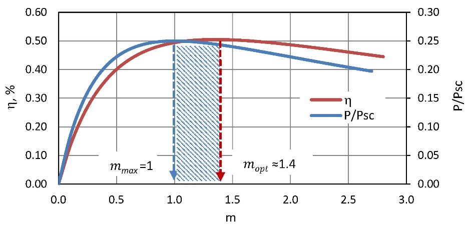
In practice, use the electric load from this range (4.8) turns out to be more comfortable than to select optimal electric load with exactly the specified value.
From the formula (4.1) with use of (4.3) it can be build a useful table for estimates of the absolute value of the maximum efficiency ηopt of thermoelectric generator depending on temperature difference ΔT (Table 4.1).
Table 4.1 Dependence* of maximum efficiency ηopt vs temperature difference ΔT on a generator.

The common conclusions from formula (4.1) and Table 4.1 are the following:
— in practice, the efficiency ηopt is almost a linear function of the temperature difference ΔT.
— one degree of the temperature difference ΔT gives about 0.05% of maximum efficiency ηopt.
Efficiency and carnot cycle
Useful information on the efficiency of thermoelectric generator should be of the following formulas for two marginal efficiency modes: the maximum efficiency mode ηopt and the maximum power mode ηmax.
For these modes the efficiency η can be written as the following:
— for maximum efficiency mode ηopt

— for maximum power mode ηmax

In both formulas (4.9) and (4.10) the first fractional multiplier is, generally speaking, the ideal Carnot cycle efficiency (∆T/Th). The second multiplier — thermoelectric factor reduces ideal efficiency of the Carnot cycle.
So, near room temperature (Tc≃ 300K) and typical Z≃0.003K-1 we have an numerical expression for the maximal efficiency ηopt

As for the mode of maximum power efficiency ηmax, correspondingly:

In other words, state-of-art thermoelectric microgenerators provide efficiency only 15.5–16% of the ideal Carnot cycle efficiency.
Here you can make an important note about the maximum possible efficiency for any heat engines used in waste heat recycling applications (energy harvesting).
Namely, the ideal heat engine working by Carnot cycle near room temperature provides efficiency only about 0.33% per degree of temperature difference (4.11).

Thus, this is the absolute maximum.
According to Carnot’s theorem, such wording [22]:
“Maximum efficiency of any heat engine may not exceed the efficiency of Carnot heat engine, running at the same temperatures of the heater and cooler.
This is an important point to general understand. To avoid posing unrealistic tasks to retrieve large efficiency with thermoelectric generators — larger than limited by the ideal Carnot cycle.
This issue will be discussed further in Chapter 7.
Chapter 5. Optimization of thermal resistance
Introduction. In this Chapter optimization of use of thermoelectric generator by coordination of thermal resistance of elements of design of the generator device are considered. As it appears, coordination on thermal resistance is in many respects similar to coordination of electric load resistance. Namely, there is an optimal solution with maximum efficiency at a certain ratio of thermal resistance of the generator module and other elements of a design.
Thermal resistance
Working parameters of a thermoelectric generator is determined by temperature difference ∆T that is created when heat is passing through the generator.

In basic formulas for thermoEMF E, efficiency η and net power Pthe working temperature difference ∆T is mentioned that is created directly on the sides (hot and cold) of the generator module.
In practice, however, this working ∆T is less than total temperature difference ∆Ts that is created at generator device by heat source relating to the envirnment, where heat is dissipated (Figure 5.1).
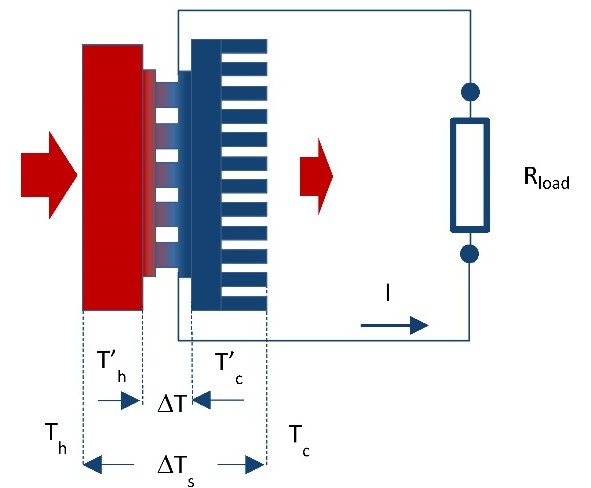
Total temperature difference:

Working (net) temperature difference ∆T on generator module is always less than total value ∆Ts:

This is due to the fact that in the design with thermoelectric generator inevitable parasitic thermal contact resistance at the crossings of the design. Particularly thermal resistance of heat sink is most important, the heat which dissipates into the surrounding ambient (Fig. 5.1).
In general

Presence of parasitic thermal resistances Ȓc besides total thermal resistance of generator device Ȓs reduces working temperature difference ∆T on TE generator module in relation to the total difference ∆Ts and, consequently, reduces its effectiveness.

Taking into account formulas (2.24) and (2.25)

In practical tasks, you must always strive to reduce parasitic heat resistance of construction, because it means a loss of working temperature difference and correspondingly — efficiency of generator.
However, as there is always non-zero values of such losses (Ȓc> 0) it is necessary an approach of optimization — the search for an optimal balance of these values Ȓ’TEG and Ȓc
Net power
Consider net power P converted by thermoelectric generator.

Here
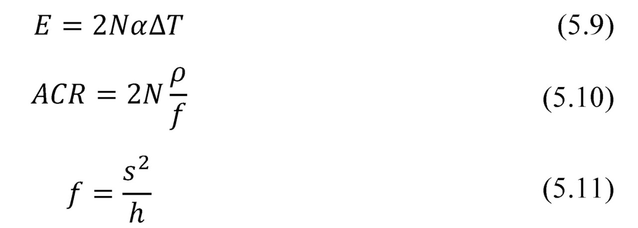
Then

With

Then the desired dependency of net power conversion P from the thermal resistance is:

Where given (5.6) and (5.7) the total dependence of net power Pon heat resistance for full temperature difference ∆Ts the system is as follows.

Maximum power
Maximum power Pmax is a particular case of the above general formula (5.16), namely, at m=1. The expression for maximum power Pmax has the following form

The formula (5.17) and graphical view (Fig. 5.2) for maximum output power Pmax from the thermal resistance Ȓ'TEG of the working generator is similar to the dependence of the power from the electrical resistance (Fig. 3.1). Namely, in both cases there are local maximums of power.
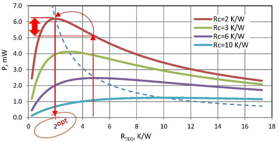
In the case of thermal resistances optimization — maximum power is achieved with equal thermal resistance of working generator Ȓ'TEGand other (sum of parasitic) thermal resistances Ȓc of the generator system.
Physical sense
Optimizing of thermal resistance has a simple physical meaning.
Generator works optimally if its heat transport capacity (thermal conductivity is inverse value to thermal resistance) and heat throughput of all other structural elements (primarily is the element responsible for heat -dissipation of past heat) agreed upon, namely, equal.
For simplicity we will consider only the element of heat dissipation — heat sink. If its heat transport capacity is less than similar parameter of generator module, less heat passes through the system as a whole the generator converts less efficient.
On the other hand, the smaller thermal resistance of heat sink is better. And generator with the specified thermal resistance works better (example, Figure 5.1 — up arrow). But then already the generator will “brake” heat flow, as its thermal resistance becomes higher than of the heat sink.
For smaller thermal resistance of heat transport, there is a different, more optimal generator that will produce even more power (Figure 5.1 — red arrow sideways). But such more optimal thermal resistance of the generator should be smaller. So according to (5.17) and Fig.5.2 it should correspond to thermal resistance of the heat exchange element (Fig. 5.1 — red down arrow).
Particular solutions
Note that maximum power is achieved when there is no loss in generator on parasitic thermal resistances. This is a particular (ideal) case when the full temperature difference drops on the generator module:

In real system with finite parasitic thermal resistance (then ΔT <ΔTs), the maximal available output power is 4 times (!) less than the maximum power output under ideal conditions.

In a case of non-zero parasitic thermal resistance the optimal case is the equality Ȓ’TEG=Ȓc. This is equivalent to the ideal case of half temperature difference on the generator module (ΔT=½ΔTs). The dependence of the power from the temperature difference is quadratic. This explains the ¼ of the optimum output power (5.18–5.19).
The construction of thermoelectric generators allows quite easily manage their thermal resistance. Namely, to obtain the optimal solution for the thermal resistance (thermal resistance change) there is a direct way to change the height and/or cross-sections of thermoelements of generator module.
Heat runs directly in thermoelectric generator through the thermoelements. Their thermal resistance is fundamental in the total thermal resistance of TE generator. Therefore, variation in height and cross section of thermoelements allows optimizing thermal resistance of the TE generator for maximum efficiency.
Thermal resistance of working generator
It must be noted that in the working generator module the effective thermal resistance, namely, the ratio of temperature difference to transported heat power differs from the thermal resistance related to the heat conductivity (Chapter 2). And approach of optimization on thermal resistance needs to be applied to the effective thermal resistance, i.e. taking into account ratios (2.24) — (2.26).
In contrast to thermal resistance of thermal conductivity ȒTEG the effective thermal resistance Ȓ’TEG of working thermoelectric generator depends on the operating mode (2.28).
— When an open electrical circuit the m=∞ and Ȓ’TEG=ȒTEG.
— At maximum efficiency mode the value mopt≈1.4 is given by the expression (4.2). If ZT≈1, the effective thermal resistance Ȓ’TEG turns out to be approximately 29% less then thermal resistance of thermal conductivity ȒTEG.

— In maximum power mode m=1 and the effective thermal resistance of approximately a third less than ȒTEG.

Since the heat resistances at maximum power (5.20) and maximum efficiency (5.21) modes differ slightly, it is often convenient to perform all calculations and modeling for maximum power mode with m=1.
Chapter 6. Design optimization
Summary. In this Chapter dependences of parameters of thermoelectric generators on elements of their design are considered. The analysis is provided on the example of the known wide nomenclature range of microgenerator modules. On these examples it is given an idea, what parameters of generators and what role they play in their efficiency and in consumer properties.
Introduction
Useful formulas are illustrated on the example of series of standard TE microgenerators developed earlier [5] in the TEC Microsystems GmbH company in relation to tasks of “low power” — energy harvesting applications.
The nomenclature of thermoelectric modules of TEC Microsystems GmbH is developed with use of classification system of thermoelectric micromodules [6]. This classification allows systematizing thermoelectric micromodules on series in compliance with their parameters and features of a design (see also Chapter 12).
Thus, logical ranks of micromodules convenient for their choice for practical applications are created.
Number of thermoelements
The number of thermoelements 2N in the generator module at the specified temperature difference ∆T and Seebeck coefficient αdetermines the key characteristic — total thermoEMF E.

The value of thermoEMF E provided by the generator determines the output voltage U in the load circuit.

Depending on value of load resistance Rload the working voltageU range of generator could vary widely.
In maximum power mode

If to increase load resistance Rload in the limit we have

Value of thermoEMF E and corerspoindingly output voltage U of generators are variable; depend on the value of temperature drop ∆T. It is not so convenient for consumers of such non-stable power supply — to electronic devices.
Always it is necessary to use electronic DC-DC converter to transform the generator variable voltage to the standard supply voltage of electronic devices.
The DC-DC converters have restrictions on the minimum input voltage which they can transform. It needs to be taken into account. And thermoelectric generators selected for practical applications must be capable to give working voltage not below the minimum threshold of the applied DC-DC converter. In more detail about the choice of a DC-DC converters see Chapter 10.
Zones of applicability of modern DC-DC converters with the minimum input voltage are given in Fig. 6.1. It is, for instance, 20 mV (Linear Technology) [3], 80 mV and 250 mV (Texas Instruments) [4].
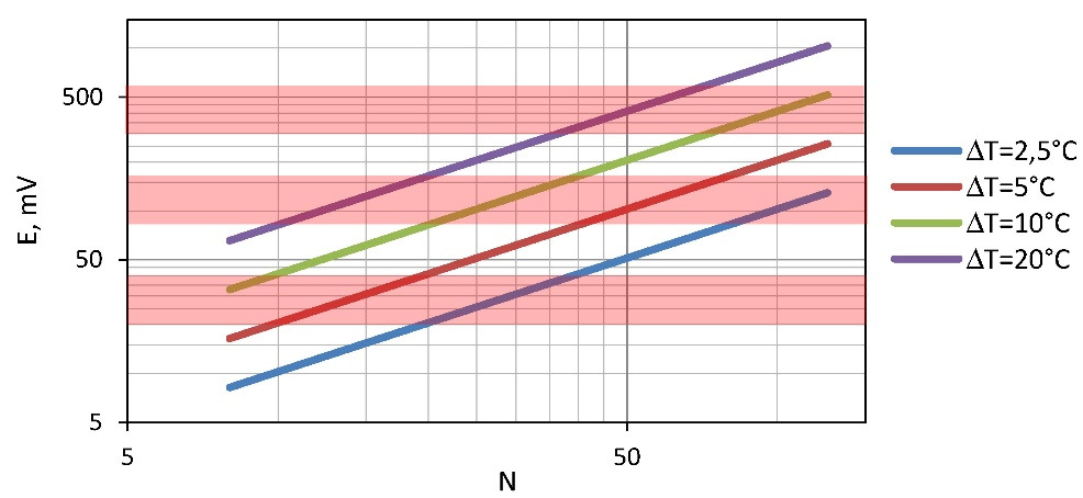
Besides, low input voltage of the DC-DC converter requires to pay additional “cost”. It is the converter efficiency. The input voltage is lower — the efficiency of transformation of the DC-DC electronic scheme is lower.
In this regard it is more preferable to use generators giving the bigger thermoEMF, i.e. generators with a large number of thermoelements (see Fig. 6.1). Besides, practical tasks sometimes force to leave absolutely optimal solutions for generator. I.e. to use electric loads with a resistance bigger, than ACR, to increase the output voltage of the generator, though by reduction of generator’s efficiency.
It means to consider efficiencies of thermoelectric generator and DC-DC electrical circuit in a combination to obtain maximal output value (see Chapter 10).
Form-factor of thermoelements
The form-factor f of thermoelements of the generator module determines its total electric resistance.

Here we neglect the additional resistance of the generator module construction (conductors, places of soldering of thermoelements, resistance of barrier layers). In most cases it is valid, as this additional resistance is insignificant usually in comparison of the sum of resistance of thermoelements (6.5).
Then

The formula for maximum power Pmax through the generator number of thermoelements N and their form-factor f has a finite shape

Thermal resistance
Thermal resistance ȒTEG of thermoelectric generator determines its overall performance.

Formula (6.8) can be converted to a dependence of maximum power Pmax vs thermal resistance ȒTEG of generator.

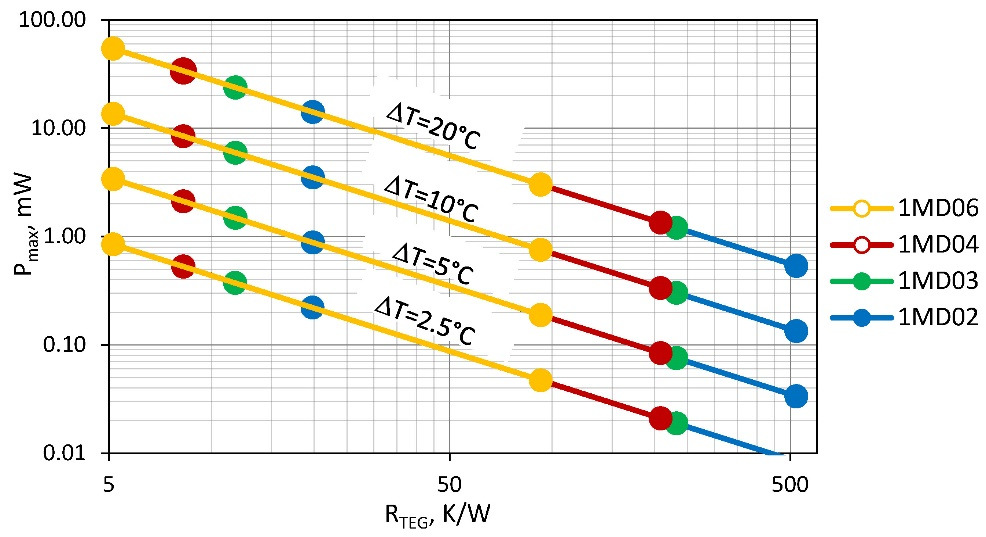
This formula (6.10) and the provided graph (Fig. 6.2) are important for understanding of features of practical applications of generator modules and the choice of optimal solutions.
The power provided by the generator depends on its Figure-of-Merit Z, thermal resistance ȒTEG and temperature difference ∆T.
— Figure-of-Merit Z is defined by properties of the thermoelectric material used in the generator module and a design of the module. For different designs of generators average Figure-of-Merit Z — it a little changeable size is at the level of 2.8…3.0⨯10–3 K-1 (Table 7.1).
— Temperature difference ∆T for a specific case is the value set up by the heat source and the environment.
— The only changeable parameter is the thermal resistance ȒTEG. It can vary widely for a particular design of TE generator just by changing the form-factor — by height and cross-section of thermoelements and number of the thermoelements.
Fig. 6.2 shows the broad range of applicability of modules of given nomenclature. It is due to an opportunity in these series to change form-factor (cross-section and height) of thermoelements and its number.
Coefficient of performance
In accordance with (2.21) the efficiency of the thermoelectric microgenerator in the modes of the maximum power (m=1) or maximum efficiency when mopt~1.4 (4.5) is determined only by the performance of the thermoelectric material — Figure-of-Merit Z, temperature difference on the generator module ∆T and averaged working temperature (Th+Tc) /2.
For practical estimates the efficiency values at averaged temperature 320K and typical values of Figure-of-Merit Z (Chapter 7, Table 7.1) of generator micromodules are given in Table 6.1.
Table 6.1 Efficiency of generator modules depending on temperature difference (at average temperature 320K).

For the small temperature differences it is possible with good precision to consider that every degree of temperature difference provides: in the mode of the maximum power the efficiency ~ 0.047%, and in the mode of the maximum efficiency ~ 0.048% of the efficiency.
It should be noted, at increasing of average temperature the efficiency falls down (see Chapter 7). For example, in Chapter 4 it has been shown that at average temperature 300K by one degree of temperature difference the efficiency is about 0.05% (Table 4.1).
From Table 6.1 it follows that at a temperature slightly above (320K) — efficiency per one degree is slightly lower (~ 0.047%). It is explained by temperature dependences of thermoelectric material of the generators (Chapter 7, Fig. 7.3).
Heat flow density
At given efficiency the total converted power will be determined by heat flow Qc passing through the generator module. And it is set by the capacity of the heat source and the heat transport “capacity” (inverse of thermal resistance) of the generator itself. These characteristics must be coordinated.
For coordination it is useful to operate with value of heat flow density on unit of the heat giving surface and heat flow density which is passed by unit of generator surface.
Heat flow density (2.26) is given by the formula:


For practical estimates the data for heat flow density for various types of generator micromodules are provided in Table 6.4.
Thus, at the given temperature difference and the given characteristic of heat conductivity of material of the generator module, heat flow density depends on density of packing of thermoelements in the module design (6.11). The more densely they are packed (less gap between thermoelements), the generator is more powerful.
Density of heat flow passing through the generator characterizes its specific power. This specific characteristic allows calculating of absolute values of a heat flow through the chosen generator module.
Comparison of heat flow density of the heat giving surface and density of a heat flow via the generator gives the answer to a question whether it is necessary in a design of the generator device the big surface of heat collecting. I.e. whether it is necessary to collect and concentrate heat on the generator for his effective work.
Table 6.2. The density of heat flow through different types of generator micromodules at various temperature differences.
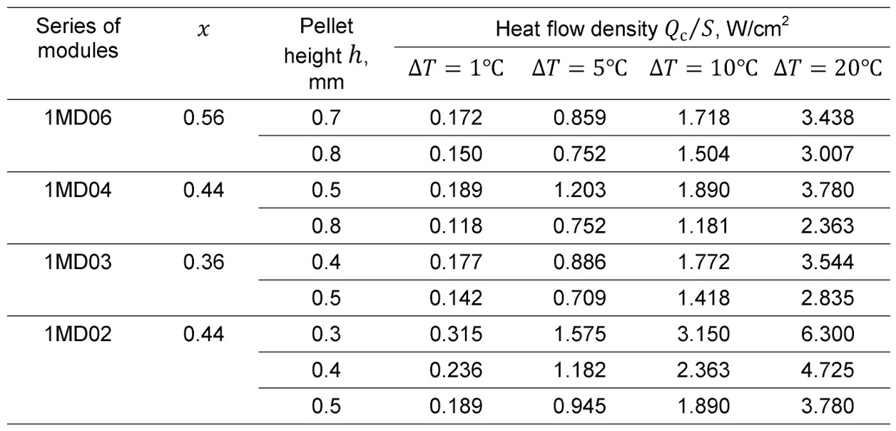
From Table 6.2 it is seen that heat flow density via the generator micromodule can reach several units of W/cm2. To provide such power densities may require heat flow concentrators from heat source (case of low power heat source).
This is important issue for energy harvesting tasks, where low-power heat sources usually have very small values of heat flow power density.
Illustrative example — recycling of the human body heat. Heat flow density of such kind of heat “source” is small compared with tabular values for the microgenerators (Table 6.2) — no more than 10–1…10—2 W/cm2. Clearly, the generator device in such tasks should include heat flow concentrators. Moreover, the area of such a hub should significantly exceed size of the generator micromodule.
Another example is soil generators which utilize heat flowing in the upper layers of soil in the daily cycle. Here the heat flows have values at the level of 100W/m2 (0.01W/cm2). It also requires the concentration of heat for the supply to generator micromodule.
Another important task is to effectively dissipate heat passed through the generator. If this is not achieved, the useful heat, transported through generator system, limited to a size not more than wasted on a radiator.
Here it is also important to the specific characteristics of the density of heat flow through the radiator -" flow capacity” of the radiator. It is necessary to calculate the dimensions of the radiator (see Chapter 9). In many practical cases, dimensions of a heat sink should be also noticeably larger than the generator micromodule.
Chapter 7. Thermoelectric materials
Summary. In this Chapter properties of the thermoelectric materials applied in microgenerators for energy harvesting are considered. On the working temperature range of these tasks, such generators can be classified as “low-temperature”. Besides in this temperature range the majority of thermoelectric coolers works. Therefore also thermoelectric materials for generator applications are used same, as for thermoelectric cooling — solid-state solutions on the basis of the Bi-Sb-Te.
Typical parameters
As shown above (Chapter 6), thermoelectric material properties of the thermoelements play decisive role in the parameters of efficiency of microgenerator modules.
Therefore, when designing of microgenerator it is necessary to pay great attention to properties of thermoelectric material from which they are should be made.
Application of energy harvesting means heat recycling from heat sources of low power, small temperature difference relating to the environment. Approximately this temperature range can be defined as ~250 … 450K (-25… +180°C).
In this regard an analogy arises to other field of applications of thermoelectricity — thermoelectric cooling. Practical temperature range of thermoelectric cooling is approximately similar stated above.
It explains that for thermoelectric generation in energy harvesting tasks practically the same thermoelectric materials on the basis of solid solutions of Bi-Sb-Te, as successfully can be applied as to thermoelectric cooling. Such thermoelectric semiconductor materials have maximal efficiency in this temperature range.
Key properties of thermoelectric material are combined in expression for its Figure-of-Merit Z.

Typical parameters of thermoelectric material applied for manufacturing of microgenerators and microcoolers are given in Table 7.1.
Table 7.1 Typical parameters of thermoelectric materials of p-and n-types at 300K.

Also temperature dependences of properties in the working temperature ranges are important for detailed calculations and modeling of real devices operation.
For convenience of calculations and mathematical modeling temperature dependences can be presented in the polynomial form.
Temperature dependences of properties of the applied thermoelectric materials are described well by a polynomial of the 3rd order of general view as following

Detailed data for typical polynomial temperature dependences of the major properties are provided in Table 7.2. In Fig. 7.1 these typical temperature dependences are graphically presented.
Table 7.2 Polynomial coefficients of temperature dependences (7.2) of properties of thermoelectric materials.

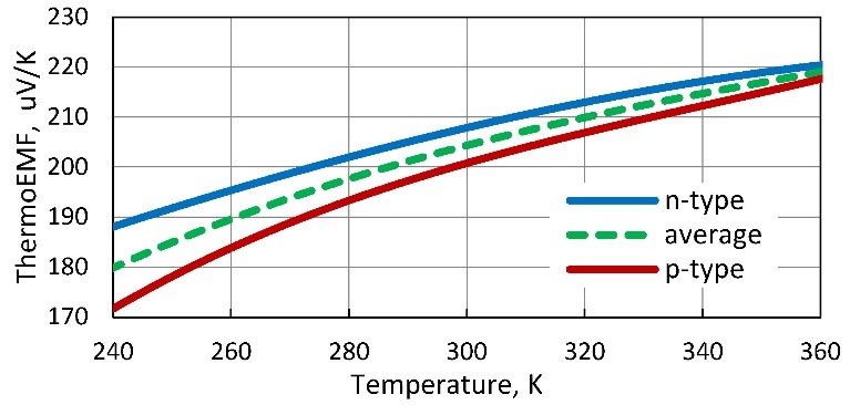
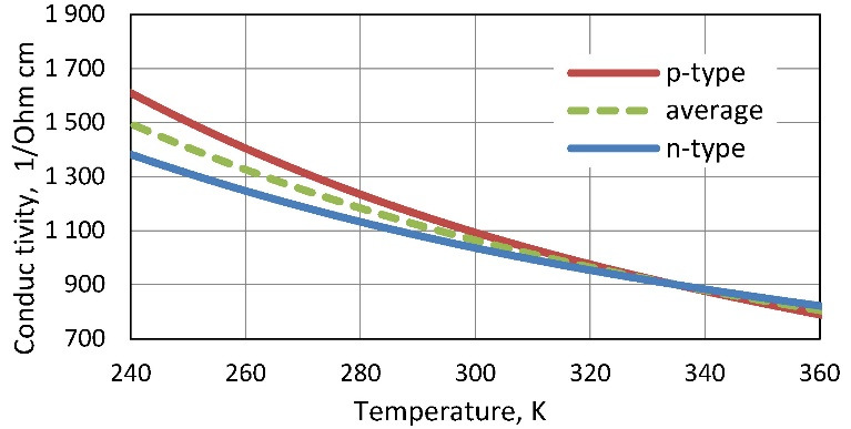
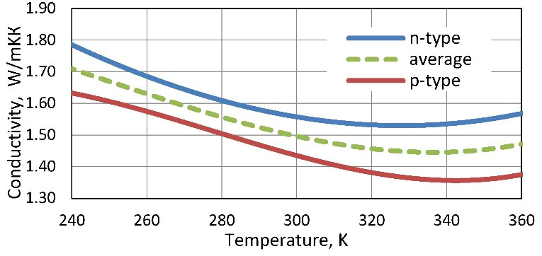
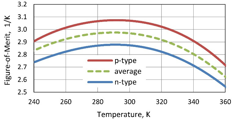
Figure. 7.1 Temperature dependences of thermoelectric materials properties: Seebeck coefficient (a), electric conductivity (b), thermal conductivity (c) and Figure-of-Merit (d).
In calculated parameters of thermoelectric microgenerators average characteristics of pair of thermoelements of n-and p-types are applied. Therefore temperature dependences of properties of materials of both n-and p-types and these average dependences are given in Fig. 7.1. Average dependences characterize properties of p-n pair of such thermoelements. In mathematical formulas for parameters of thermoelectric generators such average properties on p-n to pair of thermoelements are just used.
On the presented temperature dependences it is necessary to make several important remarks.
Voltage
Voltage U provided by generator linearly depends on thermoEMF E, defined by Seebeck coefficient α.
Бесплатный фрагмент закончился.
Купите книгу, чтобы продолжить чтение.