
Бесплатный фрагмент - Piston Engines of the New Generation (Without turbo — supercharging)
The book gives an analysis of mistakes in the generally accepted calculations of piston rings, carried out without taking into account the influence of physical laws on the operation of rings (gas dynamics, hydraulics and thermodynamics). Based on the analysis, the formula of determining the piston ring height was initially obtained. Essentially new designs of “piston devices” have been developed, in which the sealing and oil-removal piston rings are located in one piston bore located at the top of the piston. Integral construction of the piston device increases the efficiency of the engine, its power and life, reduces fuel and engine oil consumption, improves the environmental characteristics of the engine and eliminates the need for turbocharging.
The book presents updated and revised information on previous editions, adapted to the features of powerful and heavy-duty engines and compressors. The temperature changes in the shape and dimensions of the cylinder, a new piston rings combined into one contraction reduce to a minimum mechanical friction losses, to increase the engine power and resource, to reduce fuel consumption, to increase oil replacement terms, to improve ecological indicators of the engines. The design excludes application of a turbo-supercharging. The modernization concerns the cylinder-piston group of the engines or compressors, and it does not require fundamental changes in technological processes. The conditions have been created for the use of water in engine processes, and the increased competitive advantages of two-stroke engines was justified.
The book will be useful for the engineering and technical workers of motor-building enterprises, for scientists and specialists on piston devices, for students in higher and secondary educational establishments, for students of faculties and Institutes of advanced training, for driving schools when studying the design of the engines.
About the author
Anatoly Druzhinin Matveyevich, born in 1935, Candidate of Technical Sciences, Associate Professor of the Kazan Scientific Technical University named after A. N. Tupolev. Professional technologist for aviation, rocket engines and internal combustion engines. The problem of increasing the internal combustion engine efficiency has been exploring for more than 30 years, the first invention: Piston seal for ICE, Authors’ certificate, SU, No. 1388572, received in 1986. Inventions: Cylinder piston group of internal combustion engines, patents No. 2624376, 2017 and No. 2,651,694,2018 include all the innovations developed by the author. Totally there are 36 inventions and 6 patents for utility models.
The results of the research have been published in 8 issues of the scientific and technical journal “Russian Engineering Research”, translated into English and distributed all over the world. Two books have been published: Cylinder-Piston Group of the Engines and Compressors: 100% of Innovative Elements CPG/Anatoly Druzhinin. — [B. M.]: Publishing decisions, 2016. -238 C. and Modernization of the Internal Combustion Engines: Cylinder-piston Group of the New Generation, M.: Infra-Engineering, 2017. -150 C.
Druzhinin was awarded a Certificate “For the Best Innovative Idea” A new piston seals for the internal combustion engines” of the Republican competition “50 Best Innovation Ideas of the Republic of the Tatarstan”, 2006.
The book “How Make the Engine Better. New Piston Rings” is a participant of the Moscow International Book Fair, 2017.
The author
“Theory without practice is dead”
Practice is poor without theory. The harmony of theory and practice is the way to perfection”
Preface
The book presents a new edition of earlier published works of the author. The Russian name of this book is inherited from the article “How Make the Engine Better?” which was published in a very authoritative magazine “Russian Engineering Research”. The magazine is included in the list of approved by VAC RF for the publication of works of applicants of academic degrees [1]. The journal is translated into English, reprinted and distributed worldwide by Allerton Press (USA).
It is necessary that the information must be interesting for theorists and practitioners, specialists of the internal combustion engines, to publish an article in such an authoritative journal. Such grounds were. So the series of articles were published, not only in this journal but also in the profile journal “Automotive Industry”.
The book represents a new revision of another author’s book “Cylinder-piston Group of Engines and Compressors: 100% of the Innovative CPG Elements [3]. The contents of the book complement with new information, on inventions was received, the most significant practical proposals, designs, and justifications for their technological realization was reflected.
As a result of many years of searching for the reasons for the low efficiency of the engine, the specialist technologist found a fundamental error of the designers in the most important part of the design of the internal combustion engine (ICE) in cylinder-piston group (CPG).
This mistake claimed a scientific and technical sensation, because for the first time one of the main evidence of this event was published-the gas dynamics scheme of the piston compression ring. Which was opened a new direction in the design of the CPG elements for piston machines of various sizes and purposes.
The gasdynamic scheme and, based on its analysis, the formula of piston ring height determining, made it possible to supplement with the new data scientific and technical and educational literature devoted to solving problems of increasing the efficiency of the cylinder piston group and the engine itself.
In this publication, the attention of specialists is focused on the behaviour of gas dynamics at different cycles of the engine operating cycle. There is a really perspective to starting to improve the engine, in the designing and production process and in use during scheduled or unscheduled repairs.
More than 10 years passed, but the interest in the scientific community, has not appeared. The magazine articles and the textbooks published by the author remain unused. The mystery that the author had to decide and he had to believe he decided it. All this is described in more detail in the proposed edition.
In recent years, the human attitude towards scientific and technological progress has fundamentally changed. The problem of increasing the efficiency of lCE, the need “make the engine better” may be most revealing.
The author had to face with some problems of which did not help to solve the problem of improving the engine efficiency. Some approve principle changes in design others do not. We’ll try to understand these contradictions.
Start from the beginning of the product creation, with designers. Designers often develop a more complex design, forgetting that “simplicity is the sister of talent” and “the best is the enemy of the good”. In our work there is a concrete example, the “turbo-supercharging” of engines which is actively advertised and universally applied. The inexpediency of using the “supercharging”, the author tried to explain in his work [2].
The State Standards were one of the main causes of the artificial “brake” in the theoretical and practical researches. The author sent an article “Which GOST Standard is Better” in the Russian Standard and in the journal, the “Russian Engineering Research”. The editorial board after a long study, without any explanation, removed the article from the publication. The article has already been announced in the media, it was decided to place it in this book, believing that the reader would understand why the article had not published and including whether to use these Standards.
The manufacturer is the next stage in the creation of ICE. The task of the manufacturer to produce what the designers created. But that’s not quite true. They are not interested in the “simplicity” of the design. They are interested in more difficult technique with the higher cost and with great demand of its products. Maybe they want that the engine resource will be bigger. In fact, the less product’s resource, the greater the number it is planned for release.
There are a large number of people who do not want to increase the engine resource. It is a services and repair shops. Accordingly, these are millions of jobs. For the increase of which the state so insists.
Reduction of fuel and oil consumption does not inspire oil and fuel manufacturers. This all leads to a decrease in the receipts of taxes to the state budget.
In conclusion, it is possible to note that: only for the consumer and, perhaps, for the ecologists are important to have a powerful, highly resource, economical, and ecologically pure engine.
There is a violation of democratic principles, that is, a minority wins, but the whole of humanity is losing.
Nevertheless, science cannot stop, and to some extent it is confirmed by this work.
Introduction
In the world practice of engine building, there are more than a billion units of only automobile engines in operation, a huge number of powerful and super-powerful marine diesel engines, stationary power plants of civil and military use are used.
The fundamental changes in the design of the cylinder piston group engines, presented by the author, will increase their effectiveness, resource and competitiveness. The book presents the results of studies of processes occurring in the engine cylinder, affecting the efficiency of the engine, the criterion of which is usually considered the efficiency of the engine.
It is clear that efficiency, which has now reached even 0.5, with the available scientific and technical achievements, cannot correspond to the energy product of the 21st century. There is a suspicion that not everything in the ICE (internal combustion engine) is good as theorists and practitioners consider. Obviously, there are principal reasons, probably of a subjective nature, that seriously affect the working processes in the cylinder-piston group. The author faced a task: to determine these causes and to try, if possible, to eliminate them. As studies have shown, there have been opportunities like this before and now.
There is no doubt about the urgency of the solving problem. Despite the emerging alternative ways and designs of engines, the dominant replacement of internal combustion engines in the coming decades is not expected, especially in such a huge country as Russia. To increase the efficiency of piston machines is not only a technical and economic task, but no less, and for large megacities, even more — an acute environmental challenge. In modern engines, less than half of the burnt fuel is used to perform useful work, and most of it negatively affects the biosphere.
Increased efficiency and resource, accompanied by the minimum allowable amount of harmful and polluting impurities in the exhaust gases, can translate ICE into the category of new generation engines. For specialists it is quite obvious that the cylinder-piston group basically solves this problem in the engine, in the interior of which physical, chemical and mechanical processes are performed. The effectiveness of these processes depends on the state of the kinematic system, its main elements “cylinder-piston rings-piston”.
It is known that the efficiency of an energy product depends on the various losses that accompany its work. The main losses in the engine operation are “gas leakage”, i.e. gas-dynamic losses, mechanical friction losses and thermal losses-thermodynamic losses. Approximately, even the magnitude of these losses, and the place of their origin is the GPG of the engine are known.
The cylinder piston group is the weakest link in the modern engine. With the failure of the CPG there is a necessity to perform engine overhauls. And the most vulnerable part of the CPG is the seal between the piston and the cylinder, which affects all processes occurring in the engine.
There are few specialists, scientists, practitioners who doubt that the modern internal combustion engine can be attributed to the latest achievement of science and technology of the 21st century. As researches have shown, the modern engine is considered perfect, there are no basis [3], [4]. The developers of ICE have not achieved the harmony between practice and theory. Uneconomically low efficiency of the engine, stopping at around 0.4, is evidence of a lack of serious theoretical developments in the design of the cylinder-piston group.
The problem of ICE effectiveness concerns the absolute majority of mankind. A huge number of different transport and special means using piston technology generated a large number of manufacturing firms and associations, small and medium businesses, which employ millions of jobs.
The quality of the equipment purchased and expensive is essential for determining demand and responsible supply.
Most often, the products are evaluated by the quality of its manufacture. For the energy product, the quality of the manufacture is also important, but the predominant characteristic must be its efficiency, based on the quality of design, construction and operation.
The main work in the kinematic scheme cylinder-piston ring-pistons produces a piston with very responsible structure elements-the piston rings. The cylinder, despite its significance, is a relatively static element of the engine design, the changes of which can be envisaged and reflected in its shape, size and technological processes. Therefore, the focus is on the simplest kinematic system of the ICE for the “piston-piston devices”.
Designing the new engine, or carrying out modernization of the engine in the course of scheduled or unscheduled repair, it is necessary to expect maximum efficiency which has to be significantly increased, that is the efficiency (E) of the engine has to be obviously more than 0,50. To increase the efficiency of the engine, it is necessary to exclude, or substantially reduce, all of the above losses.
The Internal combustion engine is not only the mechanics but also the physical processes that ensure its operation. The physical processes, in many ways, determine the mechanics of the engine, its shape and sizes, which then form the engine’s content, its technical and economic characteristics and its ecological performance.
The low efficiency of the engine is unacceptable-evidence of great losses and, as research has shown, most of them occur in the cylinder group.
This work is generally devoted to the research of gas-dynamic, hydraulic and thermodynamic processes impact occurring in the piston cylinder on main technical-economic and ecological showings of the engine.
Sealing Piston Devices
The internal combustion engine is subject to mechanical, gas-dynamic, hydrodynamic and thermodynamic influences that alter the shape and dimensions of its individual elements and parts that are in its natural and working conditions.
The developers who designing new engines, need to know what and how the physical processes affected to the transformation of the construction during the engine operation, which should be reflected in the developed projects.
The developers are not paying enough attention to these “physical processes”. We will consider in more detail what processes and in what part of the engine, cause changes. And what changes on which engine operation and its efficiency are depend.
The main source of changes in the engine is the cylinder-piston group, in which the main physical and chemical processes occur. They naturally affect to the operation of the engine. The cylinder-piston group determines not only the dimensions of the main engine elements, the connecting rod, the crankshaft and etc., but also the shape of the engine. Let’s try to figure this out.
The efficiency of any power device is estimated by the value of the efficiency, tending to unity, depending on the complex of various losses accompanying the operation of this device.
The specifics of internal combustion engines are that, in addition to the normal mechanical losses on the friction of the mobile elements of the kinematic system, there are gas dynamic losses, hydrodynamic losses (motor oil) and thermodynamic losses.
The thermodynamic changes in the engine during its operation have a significant effect on the efficiency of the cylinder-piston group. The thermodynamics changes the shape and dimensions of the cylinder, the piston, the piston rings, and it almost affects on all the processes that occur in the engine.
The engine losses may be objective, because of any physical process occurring within the construction, which is difficult for the developer and user to use during the operation of the product. But they can also be subjective because of the human factor that allows mistakes in the design, manufacture and operation of an energy device.
To significantly increase the efficiency of the engine, it was necessary to identify these errors and propose designs that exclude these losses, or reduce them to a negligible minimum. The example above shows that the opponent of the KAMAZ engine, the losses is much smaller and this naturally affects the efficiency of the engine, its shape and content.
The above losses, in general, should be attributed to the cylinder-piston engine group, which is rightly considered the “heart” of the motor that determines the technical and economic characteristics and ecological indicators of the engine. Low efficiency of the modern engine, this is, first of all, evidence of imperfection of the CPG engine and the errors committed during its design.
§1. Influence of the gas dynamics on the operation of a piston sealing ring
From the losses considered, it is necessary to highlight, as priority, gas-dynamic losses that affect the main working processes occurring in the combustion chamber and in the engine cylinder, as a result, on the efficiency of the engine.
The researches have shown that when analysis of various losses characteristic of the internal combustion engine and affecting on the value of its efficiency, the main task was to determine the location of each of them identify the priorities and influence on other groups of losses. Two groups of losses — mechanical and gas dynamic apply for the first post.
Let’s start with the dynamics. The domestic scientists and specialists mechanics, belong indulgently to gas dynamics as to the factor exerting serious impact on work of the ICE. In the best case, the gas dynamics for them is “leakage of the working gas”, determined for a single piston ring [5].
An analysis of the accuracy and value of the gaps in domestic engines shows that the theoretical calculations of the German scientist in determining the value of “leakage of working gas” have not found wide application in our country. — In the following, we consider some constructions, where the role of “leaks” is reduced to an insignificant minimum.
Turn to the materials in the domestic textbooks. “When the ring is compressed and inserted into the cylinder, it takes a cylindrical shape and exerts a pressure on the cylinder walls equal to 0,05 … 0,3 MPa (0,5 … 3 kg / cm2) and more. During operation, the pressure increases of the ring on the walls, since gases penetrating through the gaps between the ring and the piston press the ring against the wall of the cylinder”[6].
About the same, in 10 years. “The sealing is carried out by pressing the ring against the cylinder wall by the elasticity of the ring and the pressure of the gases. At the moment of flare when the piston is in upper dead center (UDC), the pressure in the groove of the 1st ring is close to the pressure Pz in the cylinder, and in the groove of the 2nd ring it is only 50% of this value. Pressure P3 behind the last ring is much smaller; it is commensurate with the pressure in the crankcase of the engine. In view of the considerable pressure of the rings on the cylinder walls, the majority of the work of friction in the engine (up to 50%, and sometimes up to 60%) falls on the rings, so it is impossible to press the rings with excessive force”[7].
The conclusions drawn by scientists on the one hand are quite obvious, and on the other hand inferior, are of a general nature, having little effect on the process of designing the piston rings. There is no answer to the main question: how, and with what efforts does the pressure of working gases in the cylinder act on the sealing piston ring?
The process of constantly changing pressure of intake air into a cylinder, then mixed together with the fuel in the combustion chamber and transfused into working gases, should be considered as a gas dynamic process.
In 2004 for the first time the author published the gas-dynamic scheme of operation of the compression ring of the KAMAZ engine on the basis of an analysis of the established attitude of scientists and specialists of mechanics to gas dynamics [1]. This is how the design and position of the compression ring look without any slopes of the upper end face and chamfers along the inner diameter (Figure 1).
It was necessary to remember and use the known physical law, in the appendix to the given case it can sound as follows:
On the free surfaces of the piston ring (upper end and inside vertical surface) located in the closed space limited to a cylinder wall, a bottom of a piston groove and its upper and lower shelves which is under pressure of working gases, there are forces proportional to the areas of these surfaces
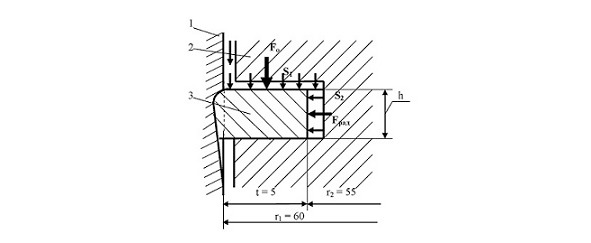
Breaking through the gap between the piston 2 and the cylinder 1 into the upper piston groove, the working pressure presses the piston ring 3 to the lower shelve of the piston groove with the gas-dynamic force F0, and to the cylinder wall by the radial force Frad and the force of intrinsic elasticity F seal. The calculation of these forces was provided in the author’s previous publications.
The most interesting can be seen in this calculation for one of the most popular domestic engines of VAZ-2190, with the following parameters: the maximum pressure of the working gases in the cylinder when the piston is at top dead center, is about Pwork = 80 kg / cm2. The dimensions are in centimetres for convenience of calculations. Diameter of the cylinder is 82 mm = 8.2 cm; the outer radius r1 is 41 mm = 4.1 cm; the inner radius is r2—38 mm = 3.8 cm; the radial thickness of the ring t = 3.0 mm = 0.3 cm; the height of the upper compression ring h = 1.5 mm = 0.15 cm.
The area of the upper butt is defined by the formula:
S1 = π (r12-r22) = 3.14 (4.12—3.82) = 3.14 (16.81—14.44) = 7.44 cm2.
The area of the inner vertical surface is defined by the formula: S2 = 2 πr2h = 6.28 × 3.8 × 0.15 = 3.58 cm2.
Multiplying the pressure of the working gases by the area values, we get:
Fo = Pwork × S1 = 80 × 7.44 = 595.2 kgf (5.95 kN);
Frad = Pwork × S2 = 80 × 3.58 = 286.4 kgf (2.86 kN).
The conclusion is obvious from the comparison of these two gas-dynamic forces acting on the movable piston ring. Twice the superior axial force reliably pressed the piston ring to the lower flange of the piston groove, depriving the radial force of the working surface of the piston ring from being pressed against the wall of the cylinder.
That is very important to note here. This pattern is observed in all cases where there is an excessive pressure on the piston. About this and not only, we will consider on the different steps of the engine motoring run. But now, running ahead, we can safely predict:
The gas dynamic scheme fundamentally changed the strategy and tactics, the theory and practice of designing internal combustion engines and piston compressors. It optimizes the size, shape and content of the engine and compressor and is reflected in the increase in the efficiency of both with its correct application in calculations.
All justifications are given in the author’s work and in this manual. The information were published and patented, brought to the attention of scientists and specialists of the motors. However, producers continue to “produce” super modern cars equipped with the engines with such significant defects. Let’s try again, to spell out in more detail the problem of increasing the efficiency of the internal combustion engines, which is not so difficult to understand, but very important for specialists.
§2. The gas dynamics at the different cycles of the engine operating cycle
The work of (that is most widespread among autotractor internal combustion engines (diameters of cylinders up to 140 mm)), the four-stroke engine consists in effective implementation of all 4 steps of an operating cycle:
— “admission” of a fresh air charge;
— “compression” of the task environment above the piston;
— the piston “working stroke” transforming the huge pressure of working gases to the mechanical work;
— “release” of spent working gases and residues, of the combustion products.
We will consider each of them in the form of a separate project, with its differences and peculiarities. But, as a result, integrated in the integral design of efficient use of the engine.
— The working stroke “admission” (suction) in the cylinder of the engine, or compressor, the estimated amount of fresh air charge.
The task of developers of any constructive element are: define the shape and size of the product, and select the workpiece material based on the conditions in which the element will work. This is a very important stage of the design, from which much will depend on the work of the product. As the initial data, developers only know one size — the diameter of the cylinder.
The principal drawback of many domestic designs (including ICE) is that the designers in their calculations take the safety factor not 1.10 or 1.20, as it should be, but 1.50 or 2.0, sometimes more than that. How important this is to the economy are known to most professionals. In the case of mass production, which we are considering, this is simply unacceptable.
Proceeding from the purpose of the working stroke “admission”, it is necessary to remember, than consolidation between the piston and the cylinder is more reliable, excluding any suction from the crankcase, the extent of discharge of space over the piston is more, the more actively there is a filling of the cylinder with rated quantity of an atmospheric air.
At the beginning of the movement of the piston in the lower position, taking into account the huge speed of displacement of the piston, above it and, accordingly, in the upper piston groove, a certain discharged space is formed. “Admission” is the only step of an engine motoring run to which influence of the gas dynamic scheme presented on fig. 1 doesn’t extend. On this step the gas dynamics is neutral therefore it is possible to approach on other design of pressure rings, proceeding only from the tasks imputed to a step “admission”.
Making rather difficult calculation of elastic forces of the piston rings, developers shouldn’t forget that on all steps of an engine motoring run the sealing (compression) piston ring has to carry out two main task and one compulsory condition:
to condense space between the piston and the cylinder, to provide transfer of heat from a superheated piston crown to the cooled cylinder, at minimum possible mechanical losses on friction.
For the piston ring, which is pressed to the lower flange of the piston groove with the previous stroke, the admission is the relaxation time, one moment. For example, with a piston stroke of 80 mm and a crankshaft rotation speed of 3000 min -1, the piston travel speed is 6 m / s, on the Formula 1 engines the average piston speed is 22.5 m / s. For an extremely short period of time, the piston ring should assume its natural position relative to the piston groove and cylinder wall. The technologists, on this occasion, have the expression: the piston ring shall “be installed” on the cylinder wall. In the process of moving to the lower dead point by friction of the ring surface of the cylinder, it is shifted to the top flange of the piston groove and is pressed to the cylinder wall with its own elasticity of the ring.
In this case it is worth using the recommendation of the domestic scientist Orlin A.S, therefore, we can take the recommended value of ring pressure on the cylinder walls 0,05 … 0,3 MPa (0,5 … 3 kg / cm2) and more [6]. As studies have shown, the expression of the scientist “… gases are pressed the ring against the wall of the cylinder” is not entirely correct with respect to modern piston rings, because they do not correspond to reality. It turns out that they lost their elasticity and were pressed against the lower flange of the piston groove with the superior gas-dynamic force F0.
In the technical conditions for the production of the “the compression piston ring” KAMAZ engine 740.1004032 is recorded: “The load applied to the arrows K, when the ring is compressed by a flexible tape to the gap in the lock, equal to the gap in the calibre of 120 mm, should be 2.3 … 3.1 kgf”. From this it follows that, despite the obvious difference in the methods of measuring the elasticity of a piston seal ring, the values of the recommended values in the textbook and the developers of the KAMAZ engine are of the same order.
It is worth noting that it makes no sense to rely neither on the recommendations of the scientist nor on the value of the “load” practiced by the KAMAZ engine manufacturers in the development of engines with cylinder dimensions about 120 mm. When calculating the elements of the kinematic system “cylinder-piston ring-piston” in modern engines, developers take into account the wear amount of each of them, thereby prolonging the warranty periods of operation of the piston rings.
The permissible value wear of the cylinder 0,15 mm, increases the gap in the lock of the compression ring of the KAMAZ engine to a size of 0.94 mm. When only the working surface of the piston ring is worn by 0.5 mm, the gap in the lock of the ring increases by 3.14 mm. In large engines, wear of the working surface of the piston ring is permitted up to 1.0 mm, which corresponds to an increase in the gap in the ring lock by 6.28 mm. Total “allowable” increase in the gap in the compression ring lock will be 7.22 mm! This is without thermodynamic, i.e. thermal extensions [4].
It is difficult to imagine how such a “thin” seal, in the design of which, by definition, there should not be any gaps, or they should be reduced to an insignificant minimum. Unfortunately, it’s hard to argue with opponents who have disarming arguments. At first, the engines “work fine”, and secondly, the compression piston rings are made exactly in accordance with the instructions of the domestic standards [8] and [9].
In this case, the question arises, why the “modern” internal combustion engine is so “good”? The answer is obvious, if you give an example from everyday life, answering a similar question: can you take a bucket of water with a sieve? Of course you can. It needs to be done very quickly and for a long time, but… the efficiency is too small.
Is the engine has a high efficiency? No! Maybe he has a small rotation speed of the crankshaft? Also, no. On the latest models of VAZ engines, small-gas turns are already over 1000 min-1!
The engines of the Formula-1 maximum power reach over 22 000 min -1, while after each race there is a major repair of the engine.
So, what are the conclusions will be drawn?
Proceeding from a purpose of a working step “admission”, it is necessary to remember, the consolidation between the piston and the cylinder, the excluding, any suction from the crankcase is more reliable, the extent of discharge of space over the piston is more; the more actively there is a fence of an atmospheric air and implementation of rated data.
First of all, it is worth paying attention to the design of the cylinder-piston group and, first of all, the design, shapes and dimensions of the piston rings. It’s incomprehensible! With a complete change in the entourage of the car, the famous AvtoVAZ, which is quite competitive with foreign models, for decades the engines are equipped with permanent piston rings, performed at the will of the standards.
It is worth noting that the equipment and technology for the manufacture of piston rings not only for the AvtoVAZ engines but also for KAMAZ, YaMZ and other engines was used by the world famous German company Goetze, which is under the patronage of the equally famous Federal Mogul concern — “the advanced European manufacturer of the engine gaskets and piston rings”. That is, all claims to poor-quality piston engine compaction should be presented not to the main designers of these engines, but to world-famous specialists with whom the “main” are in solidarity.
To this we must add the following circumstance. From the advertisement of its latest achievement, the manufacturer of the elements of CPG the Kostroma-Motordetal presented “ncMDChr (nanochrome) — a new generation coating is applied to the working surface of the upper compression and oil-removable piston rings”! Especially shocking “… and oil-removable rings”, inefficient, performing a rough operation of removing oil from the cylinder wall, in a continuous oil environment.
It is unclear why to apply “nanochrome” on them, if the working surface of the oil-removable piston ring does not wear out and without “nano”. When it is necessary to change the piston rings, along with the compression rings, oil-removable rings also fall into disassembly, but not because they have a “worn working surface”, but because the waste oil is clogged, sometimes coked, by the spiral extension of the oil-removal ring. This is especially true of the diesel engines. The inefficient oil-removal piston ring becomes generally inoperable.
This is an example of the imperfection of the widely used oil-removable ring with useless “nanochrome”. Nevertheless, Kostroma is pleased, scientific and technological progress all that is needed for the buyer to “appreciate” these innovations.
The design of compression piston rings, subjected to rigid analysis by the author, continue to “live” and “improve.” The achieved results of the research and the proposed measures for the recognized authorities of the car industry are not so “obvious”, there may be other reasons that have nothing to do with science.
The low efficiency of consolidation between the piston and cylinder is one of the most important problems of the ICE. The negative consequences of this decision are obvious, the engine can “earn” and operate normally only at huge speeds of rotation of the crankshaft, boosting the engine work. What leads to “forcing” should be known even to the motorist.
The problem of gaps is only part of the general problem of the “cylinder-piston ring-piston” system. In this case, on a working step “admission”, in the absence of excessive pressure over the piston, the mechanical friction losses of the compression rings affecting the efficiency of the engine or compressor The magnitude of the mechanical losses at the “admission” step depends on the magnitude of the elastic forces of the piston seal ring and the friction coefficient of the two kinematic elements: “Piston ring-cylinder”, more specifically, the working surface of the piston ring and the cylinder wall.
The shape and dimensions of the piston seal ring at the “admission” step depend mainly on the design value of the minimum necessary elastic force of the ring. It is necessary to determine the magnitude of the elastic force of the piston ring and the necessary material from which the ring should be made.
In analysis of the reasons for the low efficiency of internal combustion engines, it was found that in calculating the sizes and permissible deviations in the manufacturing process, in domestic engines, especially in the cylinder-piston group, there is lacks precision; therefore, as one of the measures to increase the efficiency of internal combustion engines, in the system “cylinder — piston ring — piston “was held minimization of gaps [10].
The modern piston rings, depending on their size, are mainly made of steel and cast iron. The researches, the developed theory of designing of the piston rings provide an opportunity of manufacturing of rings from other metals and alloys, and also nonmetallic materials. For example, the domestic company LLC “Compressor Technologies” advertises bronze with various fillers, various plastics as a material for manufacturing sealing and oil-removable piston rings.
At the research stage, to define the shape and dimensions of the sealing (compression) piston rings, using the results of theoretical studies, to recommend various bronze alloys and copper alloys as a material for the preparation of the ring.
— Working step “compression” of a fresh charge of air, fuel-air mix and its ignition
The working step “compression” is fundamentally different from the previous step “admission” in that by obtaining a piston ring pressed against the upper flange of the piston groove and to the wall of the cylinder by the force of its own elasticity, at the beginning of the piston’s movement to the upper position, the piston ring is shifted downward. The forces of friction of the piston ring working surface against the cylinder wall, as well as the appearing overpressure P0 above the piston and in the piston groove, further enhance the contact of the piston ring with the lower flange of the piston groove and the cylinder wall.
It is important to note, the piston ring being in the lower dead point in rather free state, is fixed in this position, appearing changes and, above all, increasing pressure over the piston. This position of the sealing piston ring relative to the piston and cylinder will remain unchanged on the remaining steps of the engine motoring run.
So, with the beginning of the piston’s movement to the upper position on the working step “compression”, gas dynamics comes into operation, according to the scheme given above to fig. 1. On a working step “admission” the design of a piston sealing ring, its shape and dimensions, weren’t of particular importance, solving the main task of effectively consolidation of the free space between the piston and the cylinder with the minimum possible mechanical friction losses.
At this stage, the developer must solve the problem of the correct use of gas-dynamic forces that will preserve the elastic forces of the piston ring, thereby guaranteeing its working capacity [11].
The author to solve this problem developed a formula, the use of which in the calculation of the geometric characteristics of a sealing piston ring allows neutralizing the negative effect of huge gas-dynamic forces on the operation of the piston ring. This formula solved the historical injustice of the subjective decision in assigning the height of the piston ring, although this decision was made by an authoritative German scientist [5].
It was suggested to “choose” for the engine the free size of the height of the sealing piston ring in an unreasonable range of sizes, relying only on the recommendation of an authoritative scientist: “Usually, the ratio of h/a shouldn’t be lower than 0,5 — 0,45” (h — height of a piston ring, and — the radial thickness of a ring).
The domestic scientists and then developers of the piston cars took these recommendations for an axiom which, obviously, those far sixtieth years of last century, didn’t demand any proofs, pilot and other studies which had to be carried out at so basic decision. As a result, instead of an incomprehensible range of sizes of “recommendations” for the height of the piston ring, there appeared “precise” indications of the domestic standards. Designers did not have to calculate the height of the sealing ring, thereby removing all responsibility for low-quality products from all “general” and “main” ones.
For example, the current GOST 621—87 for cylinder diameters of 88 mm and 130 mm “determined” the height of the sealing rings for both 2.0 mm. It’s incomprehensible! Really when developing so responsible document how the technical standard, it was unclear that from the given size of diameter of the cylinder equal to the outer diameter of a piston ring, all other geometrical characteristics of a ring depend?
How can ignore the enormous working pressures in the engine cylinders, reaching 20 MPa (200 kg / cm2) and actively affecting to the free surfaces of the movable piston ring? In these extreme conditions, the minimum change in the height of the sealing ring and its radial thickness is transformed into kilograms of force, reflecting on the performance of the piston ring and, ultimately, on the technical, economic and environmental performance of the engine. Why all this happened in detail described in the author’s publications.
To prove the published and patented objective fact, let’s show the calculation of the sealing (compression) piston ring, of a virtual motor which could be used for domestic AvtoVAZ models.
§3. The practical solutions from the theoretical conclusions
To comparing two engines of the same purpose KAMAZ and MERCEDES, the author — a professional technologist, intuitively (sometimes trusting the designers), was closer the MERCEDES engine. Of course, the importance was not the authority of the firm, but pragmatism, confirmed by many years of searching for the reasons for the low efficiency of the product, the project of which technology is implemented in the metal. Obviously, it is not necessary to convince the designers of the need for difficult searches for a simpler design that is completely would perform the tasks assigned to it.
The main advantage of the German engine, in comparison with the competing engines of “KAMAZ OOO” (Limited Liability Company) " and YaMZ TMZ of “Avtodizel OAO” (Open Joint-stock Company), is the size of its cylinder of 128 mm. The difference is small, only 8 mm, but taking into account the huge operating pressures, the power increases significantly, so the competitor was allowed to provide only 6 cylinders, with all the ensuing positive consequences.
Therefore it would be possible to recommend to domestic trucks of a class KAMAZ and YaMZ to use diameter of the cylinder of 130 mm. “Kostroma MOTORDETAL OAO”(Open Joint-stock Company) is manufactured a similar piston group with a cylinder diameter of 130 mm, for the tractor engines. This measure can be implemented only on condition of fundamental changes in the design of piston devices.
So, back to the calculation of the sealing (compression) piston ring, which could be used for domestic AvtoVAZ models. Considering the strategy of design of similar engines, it was interesting to get acquainted with features of engines of Formula -1. With engine speeds of 18,000 … 22,500 rpm or more, the engine develops power over 750 PS. with a cylinder diameter of 98 mm, a piston stroke of 39.7 mm, fuel consumption of about 60 litres per 100 km.
It is not enough to copy for our engines from AvtoVAZ series, but the design strategy, taking into account the highest class of skill of the mechanics of Formula-1, should be taken into account. Now we have VAZ engines with diameters of cylinders of 76 … 82 mm, three — and four-cylinder.
Let’s finish the interrupted calculation of the effect of gas dynamics on the operation of the compression ring of the VAZ-2190 engine presented above, but already for a virtual engine with the desired initial data.
Based on our research, we can use the maximum cylinder size for VAZ engines. Author is a technologist intuitively suggests that the most preferable can be taken as a basis for further calculations — the diameter of the cylinder is 90 mm. The second, the maximum working pressure is very important for further calculations, which we transfer from the previous calculation of the compression ring of the VAZ — 2190 engine, that is 8 MPa, and for our calculations it is more convenient to operate with 80 kg / cm2.
So, we know the size of the outer diameter of the sealing piston ring. Let’s see what size of the inner diameter GOST R 53843—2010 “recommends” to us, “suggesting” the radial thickness of the ring 3.8 +0.1—0.15 mm. Therefore, the internal diameter of the piston ring will be 90.0 — 3.8 = 86.2 mm. GOST offers to take the height of the ring of 2.0 mm. Very elegant ring! Do not prove that the developers ignored the second main task of the compression ring — to transfer heat from the overheated piston head to the cooled cylinder.
Solving this problem with such a “lightweight” piston ring is problematic, since the mass of the transmitting element, i.e. the piston ring, was lost. Due to poor heat transfer between the piston and the cylinder, the author justified the inexpediency of using standard, currently used piston trapezoidal compression rings (for example, on all models of KAMAZ engines) [2].
Nevertheless, the “trapezoidal” piston compression rings continue to be produced by the manufacturer of sets of cylinder-piston group “KOSTROMA-MOTORDETAL”, equipping KAMAZ engines, YAMZ engines and many others. It will be necessary, once again, to prove the absolute axiom shown in Fig. 2, this design does not in any way resemble a piston seal ring and a structural element that, among other things, must provide the best heat dissipation from an overheated piston head to a cooled cylinder.
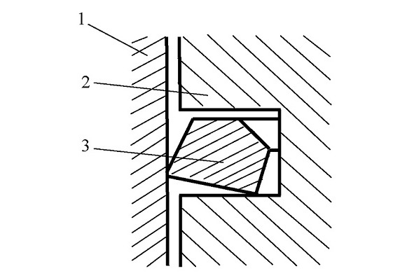
Moreover, the initiator of the “twisting”, “wedge-shaped”, and according to our GOST “trapezoidal” piston seal rings, intelligibly explained that the “twisting” rings are obtained as a result of the fact that “… the main axes of inertia formed (after tuck, bevel, facet) of the non-symmetric cross-section of the ring become non-parallel (and correspondingly) non-perpendicular to the working surface, that is, they are located obliquely.
If such ring is compressed to working size, then it doesn’t remain flat in the initial plane, and takes the dish form so that the lower edge comes out stronger, and only it comes to contact with a working surface of the cylinder (fig. 328)” [5]. In this case, the practice confirmed the conclusions of the scientist that the gas dynamic forces which are repeatedly exceeding over “mechanics”, it is possible to change the position of a pressure ring in a piston groove. The question arises, but do we need this?
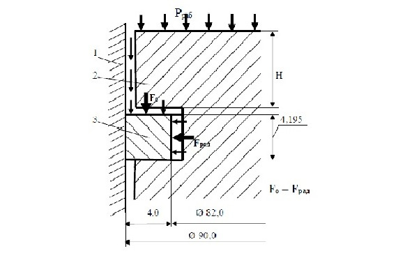
Having some experience and not agreeing with the GOST, we will carry out calculations, according to our theoretical assumptions and our intuition, we will take the size of the radial thickness of the piston compression ring equal to 4.0 mm. According to the gas dynamic scheme (Figure 1), in order to eliminate the negative effect of gas dynamics on the operation of the piston compression ring, it is necessary to equate the axial gas dynamic force F0 acting on the upper end of the ring with the radial gas dynamic force Frad pressing the piston ring working surface to the cylinder wall.
It is necessary to take into account the force of the self-elasticity of the ring, which presses the working surface of the piston ring against the wall of the cylinder Fpr.
In order to balance the gas-dynamic and mechanical systems and ensure the normal operation of the compression (sealing) piston ring, the proposed equality should be fulfilled: Fo = Frad + Fpr.
GOST proposes to accept “minimum elasticity (in the belt) of the ring 14.20 N (1.45 kgf), for the cylinder diameter of 92 mm. This parameter is set within 2.3 … 3.1 kgf, for comparison, in the technical conditions for the upper piston compression ring of the KAMAZ engine (cylinder diameter 120 mm). In the kinematic system of the “cylinder-piston ring-piston”, fundamental changes occur at our will, take the minimum necessary value, for example, Fpr = 6.0 N, that is, 0.6 kgf. Further calculations and related experiments should confirm the validity of these assignments.
To fulfil the proposed equality of forces, it is necessary to equalize the surface areas of the upper end of the piston ring S1 and the inner vertical surface S2, i.e. S1 = S2. Let’s calculate these areas. We took the value of the cylinder diameter of 90 mm, the size of the radial thickness of 4.0 mm, i.e., t = 0.4 cm; the height of the compression ring is denoted by h; operating pressure is Pwork = 80 kg / cm2.
The surface area of the upper end of the compression ring is determined by the formula S1 = π (r12- r22), where:
r1 is the radius of the cylinder, i.e., the outer diameter of the piston ring r1 = 45 mm, or r1 = 4.5 cm;
r2 is the radius of the inner diameter of the piston ring, which is equal to
r2 = r1-t = 45—4 = 41 mm, or r2 = 4.1 cm.
The area of the inner vertical surface of the ring S2 is determined by the formula: S2 = 2 πr2h.
In this formula, we take the height of the piston ring as an unknown quantity, because we have proved that the standards recommend us incorrect data. Let’s try to correct them, for this we equate both areas of these different surfaces of the piston ring π (r12- r22) = 2πr2h. The size of the height of the ring h is unknown, in this equation, it is easily determined by the formula: h = (r12-r22) /2r2. Substitute the values and get: h = (20.25—16.81) /2 × 4.1 = 3.44/8.2 = 0.4195 cm = 4.195 mm.
Define the values of the areas S1 and S2:
S1 = 3.14 (20.25—16.81) = 3.14 × 3.44 = 10.8016 cm2;
S2 = 2 × 3.14 × 4.1 × 0.4195 = 10.801286 cm2.
Now we can accurately calculate the value of the gas-dynamic forces Fo and Frad acting on the piston compression ring intended for the engine cylinder with a diameter of 90 mm. For this, we multiply the value of the maximum working pressure in the cylinder and in the piston groove by the dimensions of certain surface areas:
Fo = Pwork × S1 = 80 kg / cm2 × 10.8016 cm2 = 864.128 kgf;
Frad = Pwork × S2 = 80 kg / cm2 × 10.801286 cm2 = 864.103 kgf.
The difference Frad — F0 = 0.025 kgf, can be negligible, lying within the limits of measurement error.
We can assume that the effect of the gas dynamic forces are balanced, therefore, the negative effect of gas dynamics on the operation of the piston compression ring is neutralized. The working capacity of the piston ring is provided by the force of pressing the working surface of the ring against the wall of the cylinder, that is, by the elasticity of the piston ring. The necessary magnitude of this force can be achieved not only due to the geometric dimensions of the piston ring, but also the determination of the properties of the material from which the piston ring is made and the heat treatment, the gap in the lock of the ring in the free state.
So, we got all the necessary sizes, let’s see how the design will look on the sketch of Fig. 3. The difference from the gas-dynamic scheme shown in Fig. 1 is fundamental, both in form and content. The main thing, to what the taken measures have resulted, is clearing of a compression ring from any overloads connected with gas dynamics. To the piston ring was returned to its elastic qualities, the normal position relative to the flanges of the piston groove and the cylinder wall, normal operability. The form, content (material, thermal operations) and dimensions provided favorable conditions for function execution assigned to the piston compression ring.
The piston compression ring is designed to execution: the following tasks:
— reliable consolidation of the space between the movable piston and the stationary cylinder, excluding any gas-dynamic losses, or reducing them to an insignificant minimum;
— heat transfer from an overheated piston head to a cooled cylinder;
— minimum mechanical losses due to friction of the working surface of the piston ring against the wall of the cylinder.
1-A CYLINDER 2-A PISTON; 3-A PISTON RING
We will analyse the correspondence shown in Fig. 2 sketch of the design of a piston seal, with the well-known functional requirements for a piston compression ring.
The first remark concerning the sealing characteristics of a piston ring located in a piston groove with the presence of compulsory, technological and operational (mostly thermal) gaps. The count of the actual state of this remark, which was described in sufficient detail, in the author’s writings.
It is worth paying attention to what the size of the gaps in the kinematic system of “cylinder-piston ring-piston”, is our developers still used. The most revealing in this case can be the gap between the gap of the piston groove and the surface of the inner diameter of the piston ring, which “recommends” the textbook of 0.7 … 0.95 mm [12].
The gaps in the locks of the piston rings, through which, as is known, “up to 60 … 70% of all leaks occur in the crankcase of the engine are no less ‘impressive’”. It is impossible to understand the logic of the developers if we compare the maximum allowable clearance of 0.45 mm in the lock of the compression ring of the VAZ engine (the diameter of the cylinder is 76 mm) with the minimum, too allowable, gap in the lock of the compression ring of the KAMAZ engine (cylinder diameter 120 mm). Which one is closer to the truth? Unfortunately, both could not provide the minimum possible gaps in locks of piston rings.
— minimum mechanical losses due to friction of the working surface of the piston ring against the wall of the cylinder.
Taking as a basis the concept of “eliminating any gaps in the kinematic system” cylinder-piston ring-piston”, or reducing them to the lowest possible values”, “as one of the measures to improve the efficiency of ICE”, their minimization was patented [10].
Let’s note two important circumstances.
1. The mechanical losses to friction of the piston ring are reduced to an insignificant minimum, due to the return of the calculated elastic properties and the transfer of the sealing ring from the category of “scrapers” to normal sliding conditions of the ring working surface along the wall of the cylinder.
2. The heat removal system from the overheated piston head to the cooled cylinder has significantly changed, due to the increase in the mass of the piston ring and the sizes of the contact surfaces of the ring with the piston groove flanges and the cylinder wall.
These two, very important circumstances, reflected on the entire engine design, the rationale for this would be presented later. At this stage, attention should be paid to the height H of the piston head, called the heat belt, that is, the distance from the end of the piston to the upper flange of the upper piston groove. This value of H should be minimized, based on several requirements for the design of the piston.
It is known that in existing gaps, where the fuel-air mixture enters, due to lack of oxygen, incomplete combustion of fuel takes place, which leads to negative consequences. This is more relevant to the gaps between the piston and the cylinder, and between the ends of the sealing ring and the flanges of the piston groove. Therefore, the smaller the height of the heat belt, the less the guaranteed gap between the piston and the cylinder, the less the amount of fuel-air mixture will participate in the unfavorable conditions of its ignition and combustion, the less fuel consumption.
In addition, the decrease in the height of the heat belt leads to a natural decrease in the dimensions and mass of the piston, which will positively affect to the entire kinematic system of the engine. Moreover, the larger the diameters of the cylinders, the more effective this logical measure of perfection of piston machines.
Once again it is advisable to repeat that minimizing the altitude of the heat belt should follow the fulfillment of the above two requirements.
All this was confirmed during the pilot studies of the KAMAZ engine. It was necessary to expand the upper piston groove to install several piston rings, this could only be done by reducing the height H of the heat belt. Tests were carried out on the piston assembly drawing 740. 1004015 — 11SB, the height of the heat belt H = 22 mm, expanded to a size of 18 mm. It was impossible to assess the effect of this size, since other structural changes that together led to positive test results were also affected. From the conducted researches it is possible to draw an important conclusion. Elimination of the huge power load acting in the process of “scraping” the cylinder liner with the upper compression ring — scraper, allowed to “weaken” the fire belt. The size of the height of the heat belt should be determined not by “mechanics”, but by “thermodynamics” because the conditions have changed fundamentally. It is possible to suggest the size of the height of the heat belt for the KAMAZ engine within 10.0 mm.
Elimination of huge mechanical losses due to the transfer of “scraping” compression piston rings in the category of sliding, allowed “weakening” the entire kinematic power system of the engine, starting with the piston pin, connecting rod and furthering on the system. That, of course, will have a positive effect on the form and content of the engine.
Continuing the further improvement of the engine, draws attention to the sketch of the drawing (Figure 3) and the gas dynamic forces indicated on it, which make it possible to detect the costs of a design such as a piston ring. At first, one sealing piston ring is not enough for engines and compressors. You can use such a scheme for low-power, high-speed engines and compressors, but this is doubtful.
So, for reliable consolidation between the piston and the cylinder it is reasonable to use a minimum two piston sealing (compression) rings. But there was a problem how to arrange the piston rings. The case helped the author to solved this problem. In the late 80-es of the last century in the Republic of Tatarstan there was a problem with the shortage of pistons for agricultural machinery with a large number of the pistons removed from engines in the course of their major repair. The main reason why the inspectors removed them from service is the broken upper piston groove. They turned the help of technologists of Kazan Aviation Institute, then the author suggested simply expanding — to update the upper piston groove for two standard compression rings.
This decision helped, and the author received practical confirmation of the correctness of the chosen solution [13], which had a very good perspective.
Analyzing the generally accepted in the world practice of engine building the layout of the compression and simply sealing rings, using the obtained practical results, the technologist found it inappropriate to place the piston rings in the “personal” piston grooves.
If the piston rings were solid, maybe there would not be any questions to the scheme of their arrangement. Otherwise it was necessary to develop, the author’s accepted, batch arrangement of piston rings in one piston groove, as it is presented on fig.4.
Further studies predetermined the principle of consolidation between the piston and the cylinder. The arrangement of each sealing piston ring in its piston groove is another fundamental error in the design of the piston device. Batch placement of piston rings in a single piston bore corrects a long-term misunderstanding, with all piston sealing devices, even the smallest cylinder diameters, having at least two piston rings.
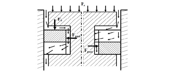
Depending on the diameter of the cylinder, the purpose of the engine or compressor, batch may contain more piston rings. An analysis of the gas dynamic scheme shown in Fig. 4, also has a significant flaw of this design. The existing gap between the upper flange of the piston groove (boring) and the upper end of the upper compression (sealing) piston ring is open to break the high-temperature working gases into the bottom cavity of the piston bore and then into the crankcase of the engine. It is obvious, to what negative consequences this leads and it becomes clear why it is so often necessary to replace the engine oil.
Moreover, it is practically impossible to eliminate the thermodynamic gap between the upper end of the upper compression ring and the upper flange of the piston groove. When minimizing all the gaps in the “cylinder-piston ring-piston” system [10], it can be assumed in the calculation of its zero value, but as soon as the engine starts to warm up, it appears and gradually increases.
There is, perhaps, the only solution, to use one of the axial expansion piston rings in the piston device that is considered in this book. This is described in more detail below, in each design there are always pluses and minuses, and the developer must evaluate it and make the right decision. However, you may be able to take advantage of one of your powerful and effective inventions, the appearance of a “pressing” ring in a sealing-piston device.
It was proposed to supplement the existing design with another piston ring with opposite physical properties, in order to block this channel of breakthrough of working gases. In contrast to the generally accepted design of the “expanding” piston rings in the world practice, the cutting rings are used; it is suggested to use compression piston rings (Fig. 5).
Бесплатный фрагмент закончился.
Купите книгу, чтобы продолжить чтение.